

How Different AWG Cable Sizes Affect Actual Current Output of QS Series Anti‑Spark Connectors
2026-10-16 11:33:15
Click:
“
How Different AWG Cable Sizes Affect Actual Current Output of QS Series Anti‑Spa
”
How Different AWG Cable Sizes Affect Actual Current Output of QS Series Anti‑Spark Connectors
Introduction
When designing battery packs for e-bikes, light electric vehicles and mobile robotics systems, engineers often focus only on the rated current of the connector itself. However, the AWG size of the mating cable plays an equally critical role in determining the real-world continuous current performance of the whole connection assembly. QS series anti-spark connectors are engineered with pre-charge function to eliminate arc during plugging and unplugging. Each QS model has recommended AWG cable sizes specified in the product catalog. Mismatched wire gauge will lead to excessive temperature rise, voltage drop and even accelerate connector contact degradation. This article explains how AWG selection changes the actual current carrying capability of QS anti-spark connectors, and shares practical guidance for proper wire matching.
What AWG Wire Gauge Means for Power Transmission
AWG, short for American Wire Gauge, is a standard system to define conductor cross-sectional area. A smaller AWG number represents a thicker copper conductor. Thicker wires have lower electrical resistance. When current flows through the cable, resistance generates heat. Higher resistance from thin wires creates more heat and larger voltage loss.
Many designers mistakenly assume the connector’s rated current is the maximum current the full assembly can support. In fact, the cable and connector form a complete current path. If the wire is too thin, the cable will overheat long before the connector reaches its thermal limit. Even if the QS connector can handle high current, an undersized AWG cable becomes the bottleneck of the power system. That is why our product catalog clearly marks the matched AWG range for every QS connector variant.
How Undersized AWG Cables Limit QS Connector Current
Using an AWG wire smaller than the recommended specification is one of the most common design mistakes. Thin copper conductors have high resistance. Under continuous high current load, the cable produces substantial heat. The heat will transfer to the crimp or solder joint between wire and QS contact terminal. Rising temperature increases contact resistance further, forming a thermal runaway risk.
In this scenario, you cannot run the QS connector at its published rated current. The actual safe output current has to be reduced to keep cable temperature within acceptable limits. Excess heat also weakens the silicone insulation of the wire over repeated cycles, raising the risk of short circuits. Anti-spark function of QS connectors protects the mating interface during connection, but it cannot resolve overheating issues caused by insufficient wire cross-section.
Impact of Oversized AWG Cables on QS Connector Assembly
Engineers may think choosing thicker AWG wires is always safer, but oversized conductors bring their own challenges. A wire that is too large cannot fit properly into the terminal crimp barrel of the QS connector. Poor crimp fit creates unstable contact resistance at the termination point. Loose crimp joints will heat up under load, which negates the benefit of thick low-resistance copper.
Large gauge cables also add mechanical stress to the connector housing. Heavy stiff wires pull on the terminals during vibration or movement. This may cause partial disconnection in dynamic applications such as e-bikes. The product catalog defines an upper limit of AWG for each QS model to guarantee reliable crimping and mechanical assembly. Oversized wire will not improve system performance and may compromise long-term connection stability.
Matching AWG Selection with QS Series Models
Every QS anti-spark connector model is validated with specific AWG wire ranges in our product directory. For smaller QS variants used in light e-bike applications, the recommended AWG is suitable for medium continuous current. Larger QS models support thicker AWG cables to unlock their full high-current capacity.
When you select the correct AWG within the catalog’s recommended range, both the cable and connector can operate at their designed thermal rating. The system achieves low voltage drop and stable temperature rise under continuous working current. Pre-charge anti-spark performance remains consistent, as proper wire sizing avoids unexpected voltage fluctuations at the moment of connection. If your application requires peak surge current, you also need to reserve extra current margin by selecting an appropriate AWG size.
Practical Design Tips for AWG and QS Connector Matching
First, calculate both continuous working current and peak surge current of your battery system. Do not only reference the connector rated current. Second, check the product catalog to pick the AWG wire within the recommended scope for your selected QS connector. Third, consider ambient temperature and cable routing. In enclosed battery compartments with poor heat dissipation, you should lean toward a thicker AWG option to reduce heat buildup.
You also need to pay attention to termination methods. Whether you choose crimp or solder connection, the wire and terminal must form a solid joint. Even with the right AWG, poor termination creates hot spots. Conduct thermal testing on the full harness assembly under real working conditions to verify temperature performance.
Conclusion
QS series anti-spark connectors deliver reliable high-current connection and arc suppression, but the achievable actual output current depends heavily on matched AWG cable size. Undersized wires create thermal bottlenecks and limit usable current. Oversized wires lead to crimping and mechanical reliability problems. Designers should follow the catalog-specified AWG range for each QS model to maximize the performance and service life of battery connection systems. Proper wire selection keeps temperature rise and voltage drop under control for e-bike, light EV and robotic power applications.
If you have any request please contact with my tech team https://www.youweic.com/
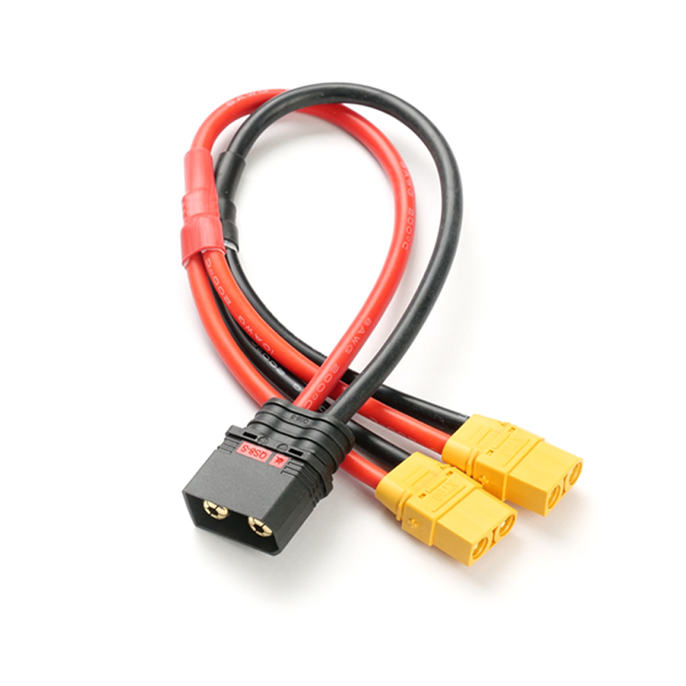









Premium Cable Solutions
High-quality cables designed for superior performance and reliability across all your connectivity needs

Copyright © 2002-2026 YOUWEI TECHNOLOGIES(DONGGUAN) Ltd. All Rights Reserved.
Copyright © 2005-2015 YOUWEI TECHNOLOGIES(DONGGUAN) Ltd. All Rights Reserved.